Rust, a Raspberry Pi and Addressable LED's
09.07.2019
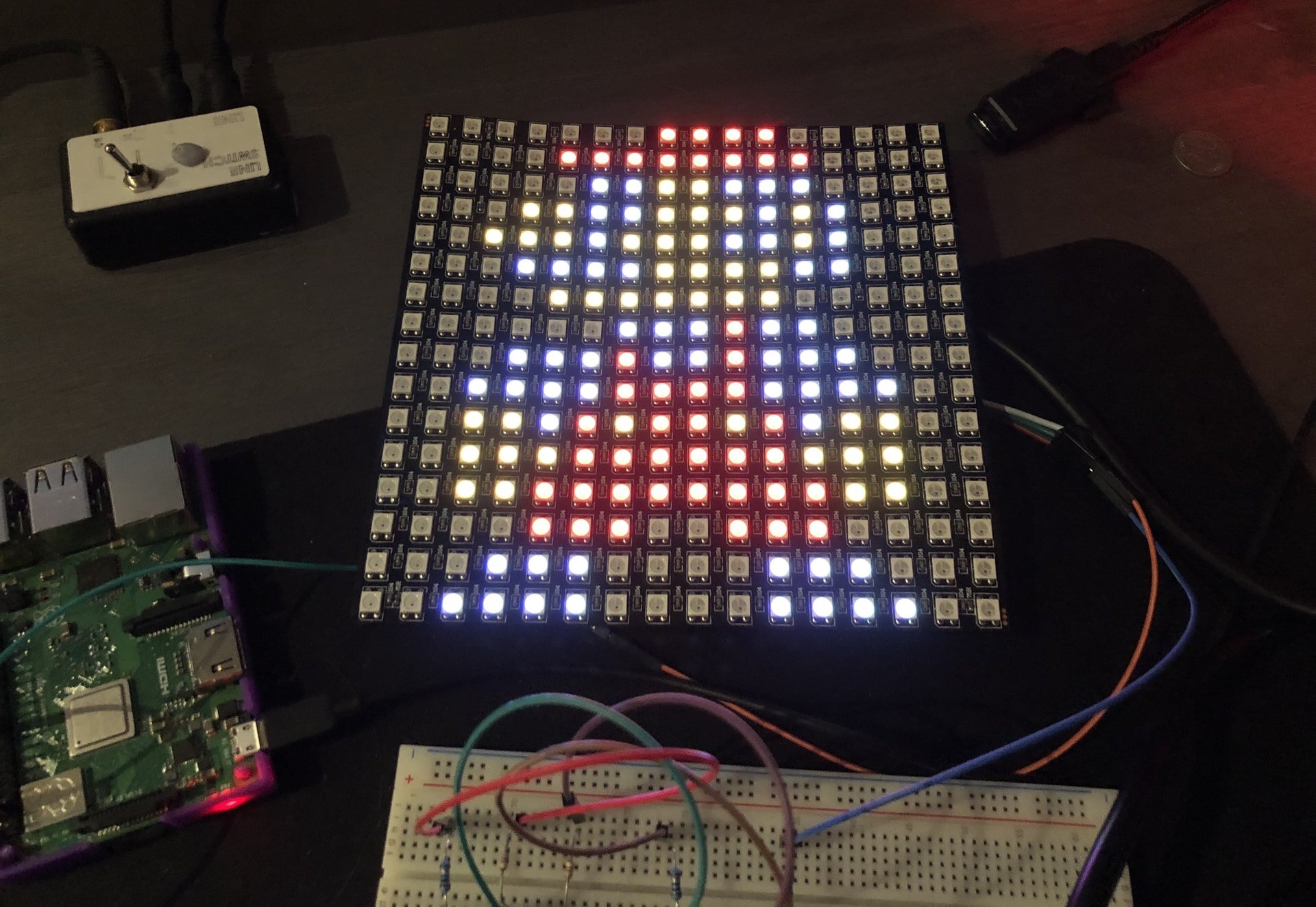
Back while I was living in New Zealand, I had a fair number of electronics projects on the go. This was one such project.
I’d been playing around with a couple of LED matrices bought from
AliExpress.
The LED’s on one of the matrices were the very popular WS2812b variant.
These panels are made up of addressable RGB LED’s soldered to a flexible PCB,
giving you three wires out the back – data, 5V, and ground.
After not being able to find a Rust library which supported these things at the time (a few have popped up since), I decided I would instead learn the protocol and try to fiddle with it myself. This is a brief overview of that experience.
The plan
The original plan was to have this thing running on something with an ARM Cortex M processor, e.g. the STM32F103C8 aka, the Blue Pill, which is incredibly inexpensive and rocking a Cortex M3. The methods below would certainly work for in that case, but for ease of the toolchain and build process I decided to prototype this with an old Raspberry Pi I had lying around.
The wiring to the panel itself it rather simple. A single 5V connection and
ground to a power supply, and then the data in pin hooked up to a digital out,
SPI capable pin from the Raspberry Pi.
The pinout of the Pi looks like so:
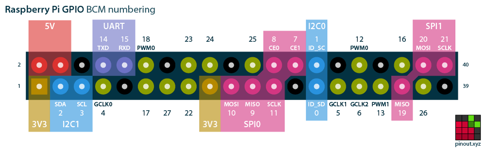
We are particularly interested in either pin 20, or pin 10. More on that later.
WS2812b Data Protocol
The WS2812b runs a protocol that can nicely be mapped to Pulse Width
Modulated (PWM) peaks
with a frequency of 800,000Hz or 800KHz. We’re able to encode a 1 using a
duty cycle of approximately 66%, and a 0 with a duty cycle of approximately
33%.
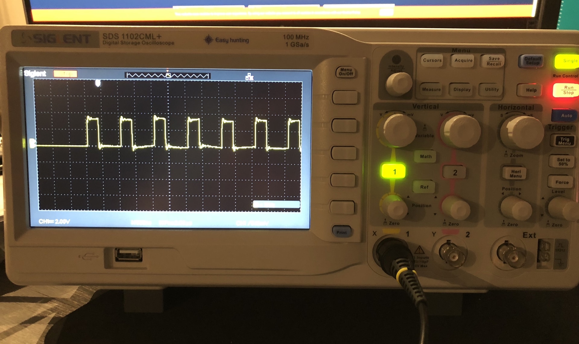
The image here shows writing a series of 0’s to the panel, indicated by the
1⁄3 high time followed by a 2⁄3 low time in the signal.
Using this, we need to send a buffer of 24 bits which is consumed by the next pixel in line. The 24 bits encode the red, green and blue hues for the consuming pixel. Once a pixel has consumed a buffer, it will forward any further bits along the chain until it receives a reset signal, where it will display its resulting hue.
The Raspberry Pi does have built in hardware PWM. However, I wanted to make it a little more difficult than simply relying on hardware implementation. So bit-banging it was.
Bit Banging
Bit banging is the process of handling all aspects of serial communication in software rather than dedicated hardware. This is really only possible when you have complete control over what is running on the processor. Timing is incredibly important, and if you’re managing clock signals in software and suddenly the OS jumps in to handle an interrupt, your program is probably going to miss its slot.
Experimenting with bit banging on the Raspberry Pi to the WS2812b’s made things pretty evident. Trying to bit bang from user space on top of the Linux Kernel, even without a garbage collector in your binary, is just not very feasible. The panel would spark to life at times, giving a pretty garbled display of colors from time to time, but its lack of precision timing meant that another solution had to be found for this experiment to get anything showing reliably.
SPI?
So with raw bit banging a digital pin off the table, I had a look at another relatively simple serial protocol (…interface), SPI. SPI is a chainable serial protocol, whose bus specifies 4 logic signals:
- SCLK: the clock signal
- MOSI: master output, slave input << What we’ll be using
- MISO: master input, slave output
- SS: slave select
Of the above pinout, we’ll only be using the MOSI pin. This is because we don’t need to transmit timing data to any other device (SCLK), nor do we need to receive any data from our panel (MISO), nor will we be chaining multiple SPI devices together (SS).
Now taking a look at the duties of the PWM signal we need to send, we can approximate the highs and lows to some multiple of 1⁄3. This means that if we run a MOSI SPI signal at triple the frequency the lights expect, then we can send a single WS2812b “panel bit” using a combination of 3 SPI bits.
e.g. To send a 1 to the panel, we could instead bit-bang 110 over SPI at
triple the 800KHz frequency.
This would give us rough timings of 416.67ns per SPI bit, and overall 1.25us
for the entire panel bit. This sits neatly within the tolerances for the high
and low sections for both a panel 1 and 0.
To get a better idea of how the panel bits are represented, I’ve drawn up a basic diagram to help get a picture of what’s going on.
Specs
The LED’s run with a scan frequency of no less than 400Hz, with a data
transfer rate of 800kbps.
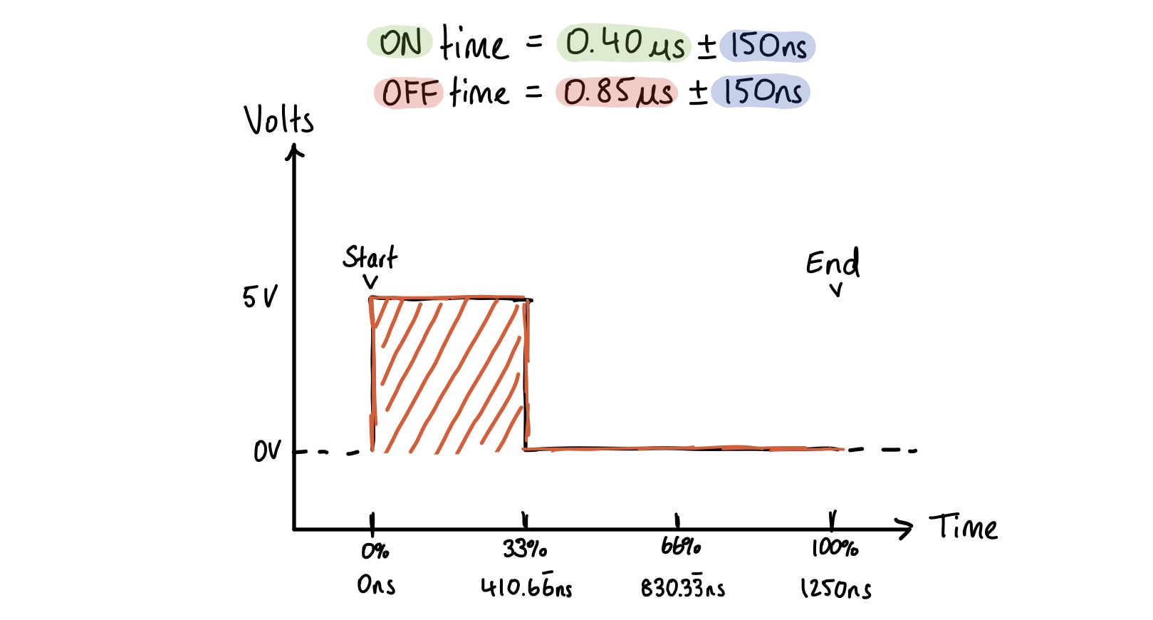
The traditional method of communication with the WS2812b is usually PWM. The duty cycle to send a single bit is:
| Bit | Time High | Time Low | Duty % |
|---|---|---|---|
| 0 | 0.4us | 0.85us | 32% ~= 33% |
| 1 | 0.8us | 0.45us | 64% ~= 66% |
A visual of the protocol is below.
Panel bit: 0
Panel bit: 1
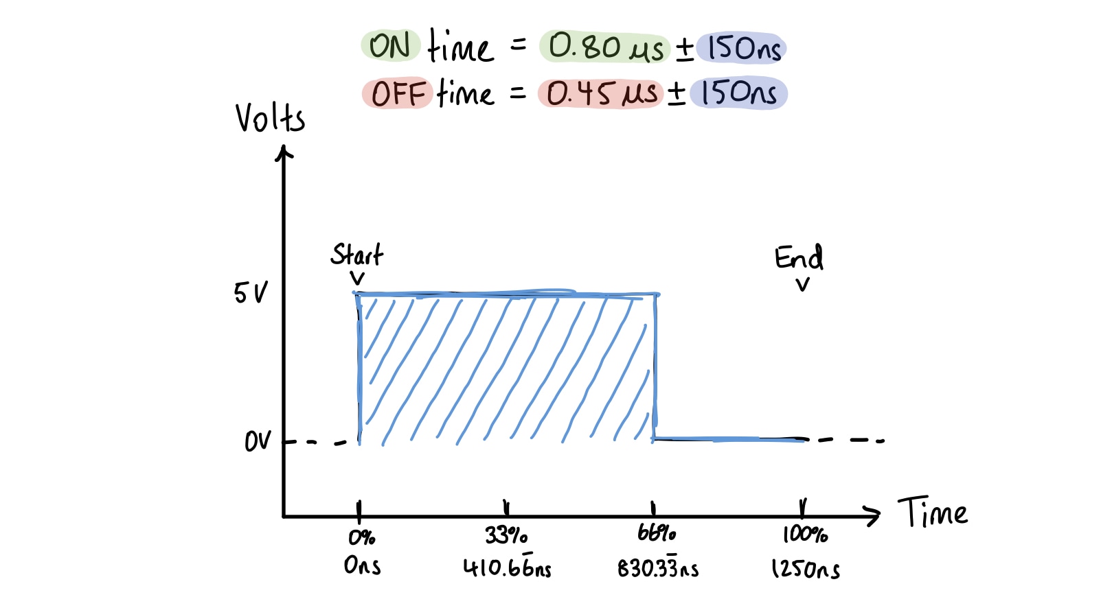
Looking at the periods above, it becomes more clear why we can approximate the
signal into 3 distinct periods, the first period always being 1, the second
being the distinguishing bit, and the last always being 0.
We are then able to encode our color channels, 3 bytes per channel, over 3
channels, totally 72 bits (9 bytes) that we need to feed down the MOSI line in
order to write a color to a single LED. We can do this repeatedly and have each
subsequent 9 bytes passed on to the next LED until we hold the line low for at
least 50us.
Implementation
The very unpolished code to make this work is surprisingly minimal, thanks to the fantastic library rppal, written by @golemparts. It allows for controlling the Raspberry Pi’s SPI ports using the Linux Kernel’s SPI device interface from Rust.
The bulk of the implementation was defining the colors, parsing them into bytes, and then translating each bit to an SPI equivalent bit to then be written to the SPI buffer and sent to the LED’s.
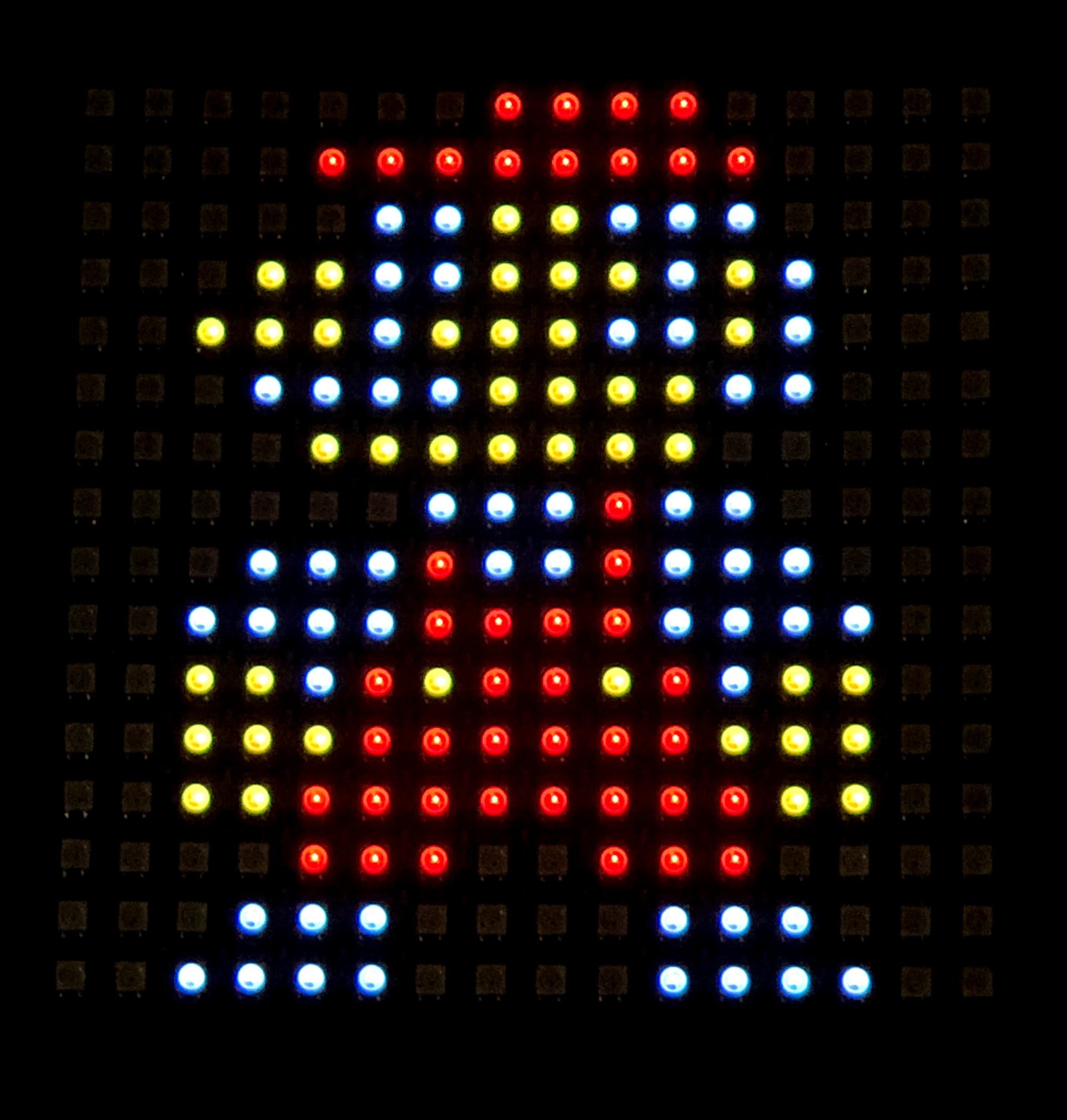
Examples